4 bit binary subtractor circuit diagram » schema digital Design and implementation of a bcd adder circuit using ic-7483 Circuit diagram for 4 bit binary adder using ic 7483
Circuit Diagram For 4 Bit Binary Adder Using Ic 7483 » Wiring Core
7483 ic 4-bit binary full adder with fast carry Circuit diagram for 4 bit binary adder using ic 7483 » wiring core Circuit diagram for 4 bit binary adder using ic 7483
Circuit diagram of full adder 7483 logic
Circuit diagram for 4 bit binary adder using ic 748374hc83 full adder ic pinout, datasheet, equivalent working, 54% off Circuit diagram for 4 bit binary adder using ic 7483 » wiring core7483 circuit diagram full adder.
Four bit adder or subtractor using 74837483 circuit diagram full adder 7483 full adder circuit diagramDesign and implementation of 10’s complement circuit using ic-7483.

Circuit diagram for 4 bit binary adder using ic 7483
Circuit diagram for 4 bit binary adder using ic 7483Circuit diagram for 4 bit binary adder using ic 7483 » wiring core 7483 full adder pdfCircuit diagram for 4 bit binary adder using ic 7483.
7483 adder full circuit bit binary addition nap parallel requires noteDesign and implement 9's complement circuit using ic-7483 74hc83 full adder ic pinout, datasheet, equivalent working, 57% offFour bit adder or subtractor using 7483.

Ic 7483 internal circuit diagram
Circuit diagram for 4 bit binary adder using ic 7483Circuit diagram for 4 bit binary adder using ic 7483 wiring digital 7483 full adder circuit diagram circuit diagram7483 full adder circuit diagram.
7483 circuit diagram full adder7483 full adder circuit diagram 15 full adder pin diagramCircuit diagram for 4 bit binary adder using ic 7483.

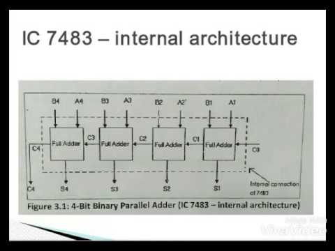
Ic 7483 Internal Circuit Diagram

Circuit Diagram Of Full Adder 7483 Logic - Circuit Diagram

Circuit Diagram For 4 Bit Binary Adder Using Ic 7483 - Wiring Diagram

Circuit Diagram For 4 Bit Binary Adder Using Ic 7483 - Schema Digital

Circuit Diagram For 4 Bit Binary Adder Using Ic 7483 - Wiring Draw

Circuit Diagram For 4 Bit Binary Adder Using Ic 7483 » Wiring Core

4 Bit Binary Subtractor Circuit Diagram » Schema Digital

7483 IC 4-Bit Binary FULL ADDER With Fast Carry | Makers Electronics

Design And Implementation of a BCD Adder Circuit Using IC-7483